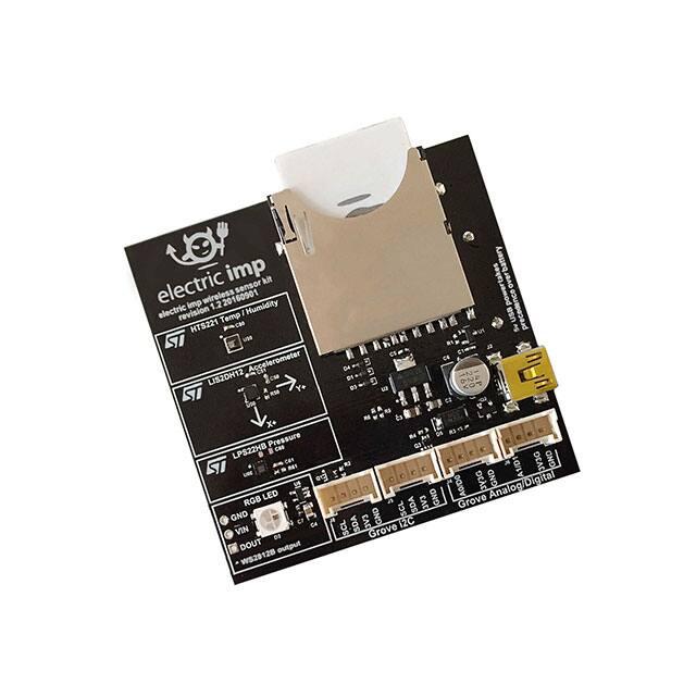
Electric Imp impExplorer Kit
The Electric Imp impExplorer™ Kit is the ideal basis for building self-contained connected
devices. It includes not only a trio of temperature and humidity, motion, and pressure sensors,
but also an RGB LED for visible feedback. In addition, it provides Grove System headers for
expansions. Two of these connectors are intended for I²C peripherals, the others for analog
and/or digital devices.
�Pinout Chart
Click for larger version
Power
The impExplorer Kit can be powered either by a standard mini USB cable fed from an AC
adaptor or a suitable (ie. powered) USB port on another device, such as a computer, TV or settop box. The Kit’s USB port is wired for power only — no data can be exchanged this way.
The underside of the impExplorer Kit is fitted with a holder for three AA batteries. If you choose
to fit rechargeable cells, please be aware that the impExplorer Kit does not include charge
management circuitry — your cells will need to be recharged externally.
The impExplorer Kit will always use USB power, if present, in preference to battery power.
Power Gate
The impExplorer Kit is power gated, with control of the gate applied to hardware.pin1. To
support high-power (5V) peripherals, such as the the RGB LED, and to make use of the Grove
Analog/Digital ports, you must include the following line at the start of your device code:
hardware.pin1.configure(DIGITAL_OUT, 1);
�Note All of the impExplorer Kit’s three built-in sensors use hardware.pin1 as their interrupt
pin, so you will not be able to use their interrupt signalling functionality — for example, to wake
the impExplorer if the temperature exceeds a certain threshold — if you also wish to make use of
the RGB LED and/or Grove Analog/Digital ports.
impExplorer Kit Sensors
The impExplorer Kit incorporates three components for environment sensing:
Sensor
Measured Quantity
I²C Address (8‐bit)
Library
Datasheet
HTS221 Temperature and humidity 0xBE
HTS221.device.lib.nut Link
LIS2DH12 Motion in three axes
0x32*
LIS3DH.class.nut
LPS22HB Air pressure
0xB8
LPS22HB.class.nut
Link
Link
*
This is not the sensor’s default I²C address, so you will need to add its address into the class constructor of its Electric Imp
library.
All of the sensors can be easily accessed in application code using the Electric Imp libraries
named in the table above. Click the library links for the latest version. Note The LIS2DH12
intentionally makes use of the LIS3DH library as these two devices are functionally equivalent.
All three sensors operate over I²C and connect to the on-board imp001’s hardware.i2c89 bus. In
addition, each sensor has an interrupt line used for indicating critical value alerts. All of these
lines connect to the imp001’s hardware.pin1: an interrupt from any of the sensors will cause
hardware.pin1 to be high.
�RGB LED
The impExplorer Kit’s RGB LED is a WS2812 device which can be accessed via the imp001’s
hardware.spi257 bus set to MSB_FIRST mode and a speed of 7500KB/s. Only imp001 pin 7 is
actually used in this role, so it is possible to make use of the Grove Analo/Digital ports (see
below), which operate from hardware.pin2 and hardware.pin5. It you are making use of the
LED and either of these pins with Grove sensors, you should configure the LED first and then
configure the Grove sensors.
The LED is best driven in application code via Electric Imp’s WS2812 library (click the link for
the latest version):
WS2812.class.nut
to the top of your device code. You will also need to add the following line at the start of your
device code:
hardware.pin1.configure(DIGITAL_OUT, 1);
Grove System Headers
The impExplorer Kit incorporates four Grove System-compatible headers, each of which
connects to a four-wire cable with two data wires (yellow and white) plus 3V3 (red) and GND
(black). For ore information on the Grove System, please see the Seeed Wiki.
�I²C
The data wires can be used to drive a variety of Grove-compatible devices, though only those
which operate over I²C are supported by the impExplorer Kit’s two Grove I²C headers, both of
which connect to the imp001’s hardware.i2c89 bus. The yellow wire provides the clock line; the
white wire the data line. Only 3V3 I²C devices are supported.
Analog and Digital
The other two headers are intended for Grove Analog and/or Grove Digital peripherals — the
two headers are connected to the imp001’s hardware.pin2 and hardware.pin5 (A0/D0 and
A1/D1, respectively). These pins connect to the headers’ primary data wires (yellow) only — the
headers’ secondary wires (white) are disconnected.
For Analog/Digital operation, you will need to add the following line at the start of your device
code:
hardware.pin1.configure(DIGITAL_OUT, 1);
Hardware Design Files (Rev 2.0)
Schematics
Gerber Files
Bill of Materials
Altium Source Files
https://developer.electricimp.com/hardware/resources/reference‐designs/explorerkit 4‐27‐18
�
很抱歉,暂时无法提供与“IMPEXPLORER KIT”相匹配的价格&库存,您可以联系我们找货
免费人工找货- 国内价格 香港价格
- 10+236.7805210+30.71120